Hardware Setup
Cables
AC Adapter for Base / Mobile
AC power adapters are usually provided for commissioning/development purposes or for statically installed SKIDER Base devices. For BASE/MOBILE-00002 they come with a round-connector (M8) for direct connection to SKIDER Base/Mobile. For legacy devices the AC adapter comes with an XT battery connector, in order to provide the same connector as a battery. A power supply cable for non-smart batteries is also needed in this case.
Power Supply Cable for non-smart battery connector (legacy)
The power supply cable allows to connect LiPo battery style connectors (XT-60/XT-30) for powering SKIDER. Make sure the connected LiPo batteries match the input voltage specification of the respective device in case you are using custom batteries.
This cable must never be connected to CBL-SPIR-00001: While this is technically possible it may cause severe damage to any device that is also connected to CBL-SPIR-00001
Integrated GNSS modules
SKIDER can use the offered GNSS RTK module to receive position information. Connect the cable to the S1 port of SKIDER Mobile and configure the software correspondingly. The S1 port of SKIDER Base can optionally also be equipped with an RTK GNSS module to generate correction data for high accuracy demands.
DJI M300 integration cable
The DJI M300 integration offers a serial and power connection to the DJI M300 allowing SKIDER to be powered by the drone and receive position information. One side of the cable is the OSDK connector of the drone while the two connectors on the other side go to the Power input and S1 port of the SKIDER Mobile.
SPIR Sensor Connector cable (CBL-SPIR-00001 and CBL-SPIR-00002)
CBL-SPIR-00001 and CBL-SPIR-00002 need to be installed between SPIR Explorer and SKIDER device. It will power the SPIR sensor and deliver sensor data from SPIRExplorer to SKIDER Mobile.
For CBL-SPIR-00001: Never connect this cable to the power supply cable. While this is technically possible it may cause severe damage to any device that is also connected to CBL-SPIR-00001
Ethernet connections
Ethernet connection cables are provided. For BASE-00001 a standard patch cable can be used. For MOBILE-00001 a custom Binder-M9 to RJ45 cable is provided. For BASE-00002 and MOBILE-00002 M12 X-Coded adapter cables are offered by us. The ethernet connection is needed on the base to connect the base to the Laptop/Device that runs the SPIR software. For the Mobile the ethernet connection is not needed during regular operation. Base and Mobile devices use the ethernet connection for accessing the web interface for software updates and system configuration.
Batteries
This section is about the newer smart battery system. For non-smart batteries please refer to the manual of the LiPo charger and adhere to general LiPo handling instructions. Make sure you understand the handling and security precautions needed for LiPo batteries without integrated battery management system.
The new smart battery systems comes with greatly improved ease of use and operation security. Please be aware that lithium batteries need nonetheless to be handled with great care. In particular, specific rules apply during transportation, check your local legislation and transportation rules.
Smart Battery Charger
The smart battery charger comes with its own short manual. Make sure you have read and understood operation procedures and feedback from the charger to identify bad batteries.
Smart Batteries
The smart batteries have a push button that enables showing the current charge status through LEDs. Note that the current charge status is also shown in the UI of a smart battery powered SKIDER device. Even though it is recommended that smart batteries don't get fully discharged they are generally protected against undervoltage and disable themselves before they get damaged due to deep discharge. When mounting smart batteries make sure that the batteries are properly locked through the cover as they may otherwise fall out leading to damaged equipment or even injuries.
Maintenance Bay
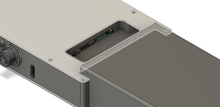
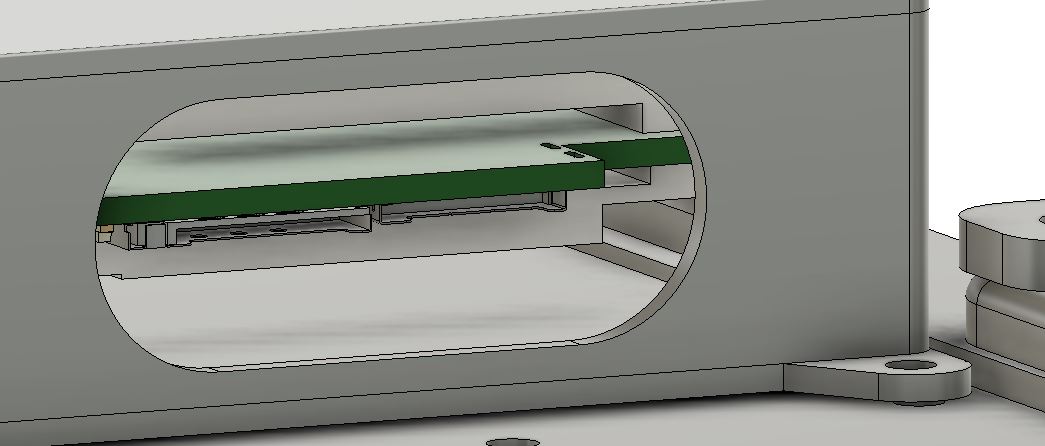
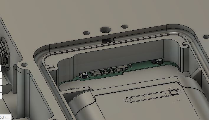
In order to insert or remove a microSD card or a Micro-SIM card, you have to access the physical slots by removing certain covers depending on your device. Remove the cover of the maintenance bay carefully. After card installation, place the cover back into place and put screws back that were previously removed.
SIM card provisioning
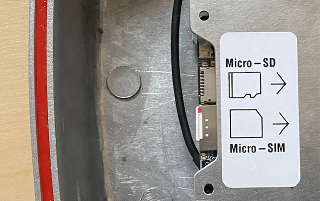
For the integrated Micro-SIM slot MOBILE-00002 and BASE-00002 contain a sticker showing the correct direction and location. Older hardware was missing this sticker - contact us in case of doubt with a picture of the side. As a general rule the metal contact side of the SIM faces the PCB. The notch of the SIM may face towards edge of the PCB or into the inside depending on hardware revision. Gently push the card until you hear a light click.
After SIM card change a power cycle of the device is required for the SIM to get detected and show up in the user interface
In order to remove the card, gently push against it until you hear a light click and the card should be free to remove.
SD card provisioning
For the integrated microSD slot MOBILE-00002 and BASE-00002 contain a sticker showing the correct direction and location. Older hardware was missing this sticker - contact us in case of doubt with a picture of the side.
As a general rule the metal contact side of the MicroSD cards faces the PCB. Gently push the card until you hear a light click.
After SD card change a power cycle of the device is required for the SD card to get used for logging while it will show up in the UI immediately
In order to remove the card, gently push against it until you hear a light click and the card should be free to remove.